Manage GraphDB From UI
1. Introduction
We are using ArangoDB as the underlying graph database. ArangoDB stands out as a powerful multi-model database that simplifies data management across different models while providing robust performance and scalability. Its unique features, such as AQL and integrated graph processing, make it an attractive choice for storing topology data and it’s visualization.
Here’s a brief overview of databases, collections, and graphs in ArangoDB:
2. Databases
In ArangoDB, a database is a logical container that holds collections and graphs and provides isolation for data. Each database is isolated from others, meaning that collections in one database cannot directly access collections in another.
3. Collections
A collection in ArangoDB is a grouping of documents. Collections can be thought of as tables in a relational database, but they are more flexible since they can store documents of varying structures without a predefined schema.
-
Document Storage: Collections store data in the form of JSON documents. Each document can have a unique structure, allowing for nested objects and arrays.
-
Types of Collections
a) Document Collections: Standard collections that store JSON documents.
b) Edge Collections: Special collections that store graph edges, which define relationships between documents (nodes).
4. Graphs
ArangoDB provides robust support for graph data modeling, allowing you to create and manipulate graphs directly within the database.
-
Graph Structure: A graph consists of vertices (nodes) and edges (connections between nodes). In ArangoDB, vertices are stored in document collections, and edges are stored in edge collections.
-
Graph Traversals: ArangoDB supports powerful graph traversal capabilities, enabling you to perform complex queries that explore relationships between nodes. You can use AQL to write queries that traverse graphs and retrieve related data.
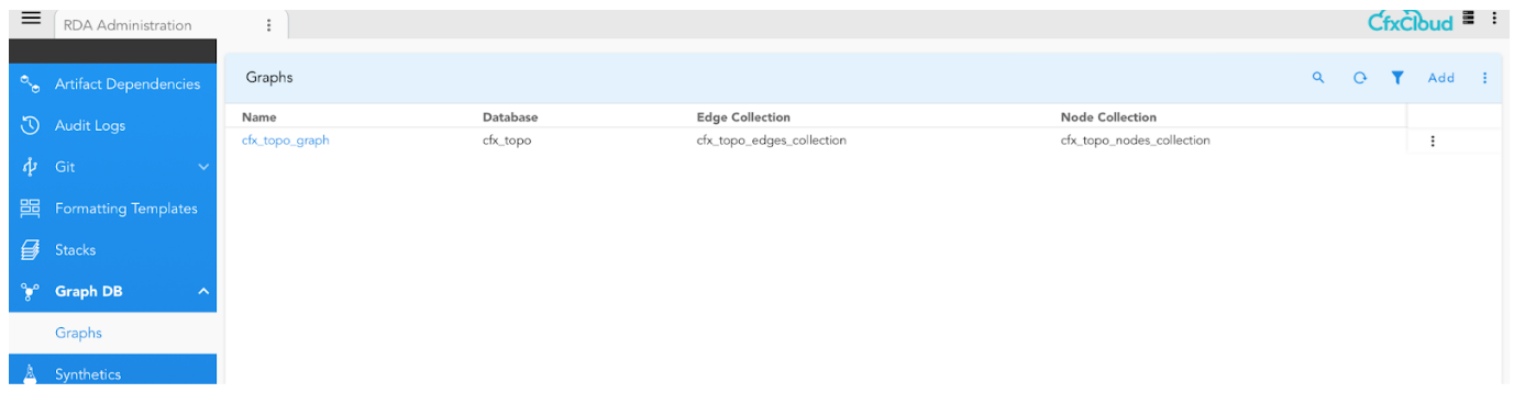
5. GraphDB UI
Navigation Path: Home → Configuration → RDA Administration → Graph DB → Graphs
To create a graph and it’s collections
Navigation Path: Home → Configuration → RDA Administration → Graph DB → ADD
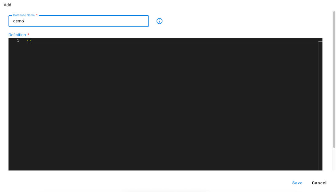
This will create a database name demo if not present and also create
Nodes collection : demo_nodes
Edges collection: demo_edges
Graph: demo_graph
We can also specify the names explicitly for graph and collections while creating graph as below
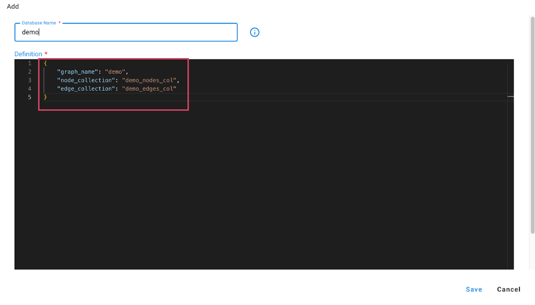
This will create a database name demo if not present and also create
Nodes collection : demo_nodes_col
Edges collection: demo_edges_col
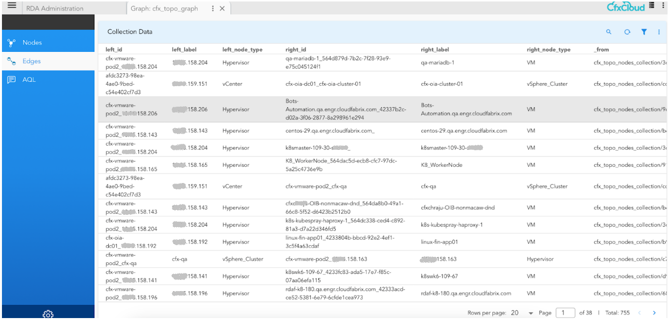
6. Graph demo

Navigation Path : Home → Configuration → RDA Administration → Graph DB → Graphs → Drill Down
Graph Nodes collection and associated documents

Graph Edges collection and associated data
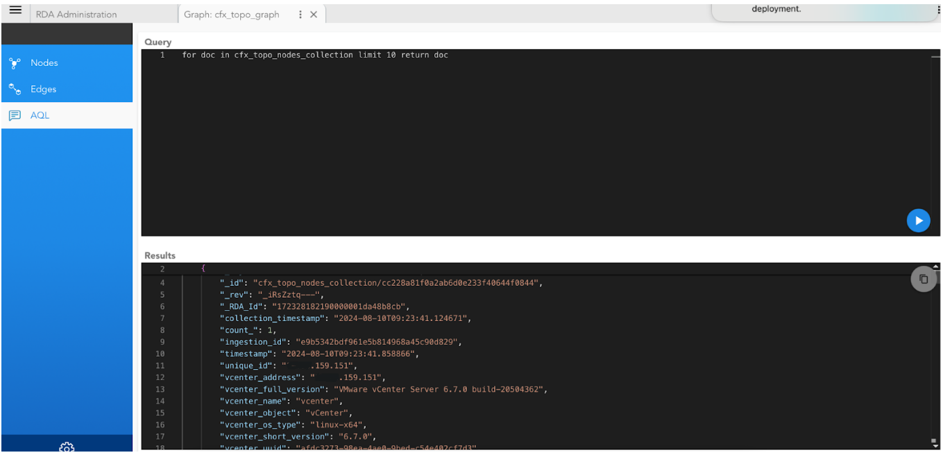
7. AQL Editor
To execute queries on graph or collections in the database
There are two Extensions that work on the Graphdb
1) Arangodb https://docs.fabrix.ai/Bots/arangodb/
2) Graphdb https://docs.fabrix.ai/Bots/graphdb/
To use ArangoDB bots, you need to add a credential of type arangodb, which the bots will utilize for their operations. In contrast, GraphDB bots automatically retrieve the necessary credentials or endpoint details from the config.json file and operate accordingly.
8. Stack definition changes to support data from graphdb
Below are the stack definition changes to support or get data from the graphdb instead of pstream.
{
    "name": "demo_stack",
    "description": "demo stack ",
    "saved_time": "2024-08-23T14:30:24.497897",
    "is_dynamic": true,
    "hierarchical": true,
    "dynamic_nodes": {
        "column_name": "node_type",
        "db_name": "cfx_topo",
        "nodes_collection": "cfx_topo_nodes_collection"
    },
    "dynamic_relationships": {
        "db_name": "cfx_topo",
        "edges_collection": "cfx_topo_edges_collection",
        "graph_name": "cfx_topo_graph",
        "relation_map": "cfx_topo_relations"
    }
}
9. Dynamic Nodes
1) column_name: node_type
Column key in the nodes data to be used to group the nodes.
2) db_name: cfx_topo
The name of the database where the node collections are stored.
3) nodes_collection: cfx_topo_nodes_collection
The name of the nodes collection within the database that holds the node data.
10.Dynamic Relationships
1) db_name: cfx_topo
The name of the database where the relationships (edges) and graphs and nodes collections are stored.
2) edges_collection: cfx_topo_edges_collection
The specific collection within the database that holds the edge data.
3) graph_name: cfx_topo_graph
The name of the graph that these nodes and edges belong to in the database.
4) relation_map: vmware_topology
Relationship map is a json structure to specify or display the multi level nodes in the topology, This is described more in detail below.
11. Dashboard Definition Changes to Support Data From GraphDB
{
  "name": "demo-topology-graphdb",
  "label": "Demo Asset Navigator",
  "description": "Demo Asset Navigator",
  "dashboard_folder": "demo",
  "version": "24.3.20.1",
  "enabled": true,
  "short_label": "Stack",
  "context_label_id": "stack_name",
  "dashboard_type": "navigation-dashboard",
  "dashboard_style": "tabbed",
  "dashboard_filters": {},
  "template_variables": {
    "NODE_ID": {
      "contextId": [
        "navigatorSelectionContexts",
        "secondaryListSelection",
        "node_id"
      ]
    }
  },
  "navigation_dashboards": {
    "tree_data": {
      "column_name": "node_type",
      "db_name": "cfx_topo",
      "collection_name": "cfx_topo_nodes_collection"
    },
    "tree_detail": {
      "db_name": "cfx_topo",
      "collection_name": "cfx_topo_nodes_collection",
      "display_column": "node_label",
      "selected_columns": {
        "node_id": "Node Id",
        "node_label": "Node Name"
      }
    },
    "showNodeIcon": true,
    "showSearchBox": true
  },
  "dashboard_sections": [
    {
      "title": "Node Details",
      "widgets": [
        {
          "title": "Summary",
          "widget_type": "portal_summary",
          "reportId": "rda.saas.topology.node_details.report",
          "max_width": 4,
          "height": 12,
          "min_width": 4,
          "widget_id": "182229d8"
        }
      ]
    },
    {
      "title": "Topology",
      "widgets": [
        {
          "title": "Topology",
          "widget_type": "topology",
          "register_search_endpoints": true,
          "reportId": "rda.saas.stack.view.topo",
          "stack": "test",
          "expand_all": true,
          "db_name": "cfx_topo",
          "node_collection": "cfx_topo_nodes_collection",
          "edge_collection": "cfx_topo_edges_collection",
          "graph_name": "cfx_topo_graph",
          "relation_map": "cfx_topo_relations",
          "height": 14,
          "min_wdith": 14,
          "widget_id": "182287d8"
        }
      ]
    }
  ],
  "saved_time": "2024-08-23T14:26:30.213622"
}
1) tree_data
a) column_name: node_type
Column key in the nodes data to be used to group the nodes.
b) db_name: cfx_topo
The name of the database where the node collections are stored.
c) collection_name: cfx_topo_nodes_collection
The name of the nodes collection within the database that holds the node data.
2) tree_detail
a) db_name: cfx_topo
The name of the database where the node collections are stored.
b) collection_name: cfx_topo_nodes_collection
The name of the nodes collection within the database that holds the node data.
3) Topology Widget
a) db_name: cfx_topo
The name of the database where the relationships (edges) and graphs and nodes collections are stored.
b) node_collection: cfx_topo_nodes_collection
The name of the nodes collection within the database that holds the node data.
c) edge_collection: cfx_topo_edges_collection
The specific collection within the database that holds the edge data.
d) graph_name: cfx_topo_graph
The name of the graph that these nodes and edges belong to in the database.
e) relation_map: vmware_topology
Relationship map is a json structure to specify or display the multi level nodes in the topology, we will discuss this in more detail below.
12. Relation Map
Relation Maps is a JSON structure that represents link between various nodes in a Graph and what other nodes need to be displayed in the topology view of a node
{
  "name": "demo",
  "relation_map": {
    "VM": {
      "INBOUND": [
        {
          "node_type": "vCenter",
          "path": [
            "Hypervisor",
            "vSphere_Cluster",
            "vCenter"
          ]
        },
        {
          "node_type": "Switch",
          "path": [
            "Switch",
            "vSwitch"
          ]
        },
        {
          "node_type": "Storage_Controller",
          "path": [
            "Datastore",
            "Storage_NVMe",
            "Storage_Volume",
            "Storage_Pool",
            "Storage_Controller"
          ]
        }
      ]
    },
    "vCenter": {
      "OUTBOUND": [
        {
          "node_type": "Hypervisor",
          "path": [
            "Hypervisor",
            "vSphere_Cluster"
          ]
        }
      ],
      "ANY": [
        {
          "node_type": "Datastore",
          "path": [
            "Hypervisor",
            "Datastore",
            "vSphere_Cluster"
          ]
        },
        {
          "node_type": "vSwitch",
          "path": [
            "Hypervisor",
            "vSwitch",
            "vSphere_Cluster"
          ]
        }
      ]
    },
    "OS_Service": {
      "OUTBOUND": [
        {
          "node_type": "Server",
          "path": [
            "Host_OS",
            "VM",
            "Hypervisor"
          ]
        }
      ],
      "INBOUND": [
        {
          "node_type": "vCenter",
          "path": [
            "Host_OS",
            "VM",
            "Hypervisor",
            "vSphere_Cluster",
            "vCenter"
          ]
        },
        {
          "node_type": "Storage_Controller",
          "path": [
            "Host_OS",
            "VM",
            "Hypervisor",
            "Datastore",
            "Storage_NVMe",
            "Storage_Volume",
            "Storage_Pool",
            "Storage_Controller"
          ]
        },
        {
          "node_type": "vSwitch",
          "path": [
            "Host_OS",
            "VM",
            "vSwitch"
          ]
        }
      ]
    }
  }
}
The Main key in the relation map is the node type we choose in the topology view(e.g., Hypervisor, VM, OS_Service, etc.).
Each node type has associated relationships to other nodes categorized by direction that needs to be displayed when a particular node type is selected in the topology view. There are mainly 3 types of directions to form a path (INBOUND, OUTBOUND, or ANY).
-
INBOUND: Indicates that the node has inward/to edges from the other specified node types.
-
OUTBOUND: Indicates that the node has outward/from edges from the other specified node types.
-
ANY: Indicates that the node can either have a to/from edges.
Taking a example of VM and Vcenter in the above relation map translates to
1) VM (Virtual Machine)
-
INBOUND
- vCenter: The VM is related to the vCenter through the Hypervisor and vSphere Cluster, indicating that the VM is managed by the vCenter via the Hypervisor.
- Switch: The VM connects to a Switch, which is linked to a virtual switch (vSwitch).
- Storage_Controller: The VM connects to a Storage Controller through a series of storage components, indicating a path from the Datastore to the Storage Controller.
2) vCenter
-
OUTBOUND
- Hypervisor: The vCenter manages Hypervisors through the vSphere Cluster.
-
ANY
- Datastore: The vCenter can access Datastores via the Hypervisor.vSwitch: Similarly, it can access vSwitches through the Hypervisor.
13. Relationship Maps in UI
We can add/view the Relationship Maps in UI
Navigation Path: Home → Configuration → RDA Administration → Stacks → Relationship Maps

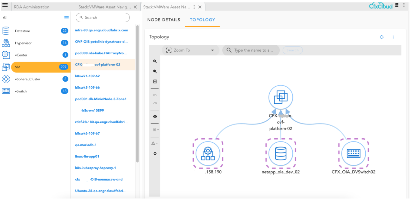
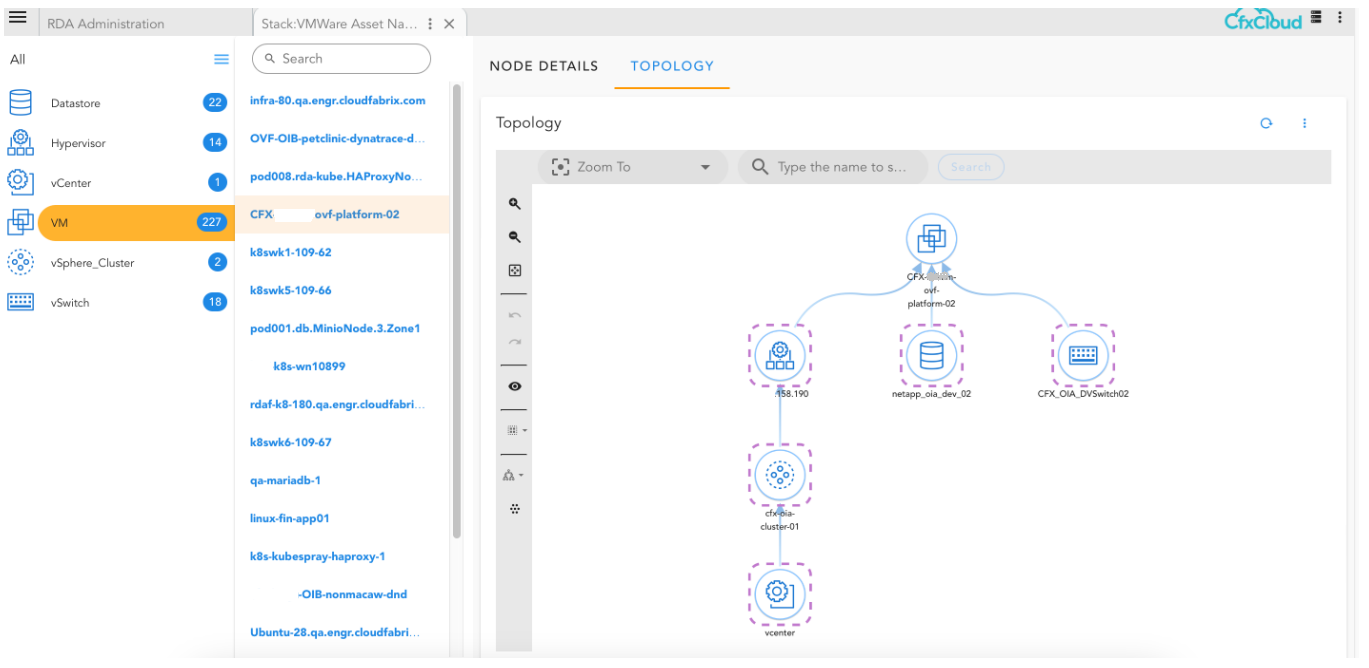
Here is the sample of how the relationship maps help us in displaying other connected nodes in the graph/topology.
14. Example of GraphDB/ArangoDB Bots
14.1 Inserting Nodes
This example demonstrates how to insert nodes from a CSV file into a database collection using a series of commands.
-->@c:new-block
    --> @files:loadfile filename = "nodes.csv"
    --> @graph:insert-nodes dbname = "radf" & collection = "radf_nodes_collection" & key_column = "node_id" & batch_size = 100
-
@c:new-block: Initiates a new command block. -
@files:loadfile: Loads the CSV file containing node data.a) filename = "nodes.csv": Specifies the name of the file to be loaded.
-
@graph:insert-nodes: Inserts the loaded nodes into the database.a) dbname = "radf": Specifies the target database name.
b) collection = "radf_nodes_collection": Specifies the collection within the database where nodes will be inserted.
c) key_column = "node_id": Defines the column in the CSV that contains unique identifiers for each node.
d) batch_size = 100: Sets the number of nodes to be inserted in each batch operation.
Note
Ensure that the key_column specified matches a column name in your CSV file that contains unique values for each node or entry.
14.2 Inserting Edges
This example demonstrates how to insert edges from a CSV file into an ArangoDB collection using a series of commands.
-->@c:new-block
    --> @files:loadfile filename = "edges.csv"
    --> @arangodb:insert-edges dbname = "rdaf" & nodes_collection = "rdaf_nodes_collection" & edges_collection = "rdaf_edges_collection" & left_id = "left_id" & right_id = "right_id" & batch_size = 100
-
@c:new-block: Initiates a new command block. -
@files:loadfile: Loads the CSV file containing edge data. -
@arangodb:insert-edges: Inserts the loaded edges into the database.a) dbname: Specifies the target database.
b) nodes_collection: The collection containing the nodes that edges are formed to.
c) edges_collection: The collection where edges will be inserted.
d) left_id and right_id: Columns in the CSV file that identify the connecting nodes.
e) batch_size: Number of edges to insert in each batch operation.
14.3 Querying Collections
-->@c:new-block
    --> @dm:empty
    --> @arangodb:query-collection dbname = "rdaf" & collection = "rdaf_nodes_collection" & query = "node_type not in ['Edge','CHASSIS']"
-
@arangodb:query-collection: Executes a query on the specified collection.a) dbname: The target database.
b) collection: The collection to query.
c) query: the filter condition as cfxql query.
14.4 Deleting by Query
This example demonstrates how to delete documents from a collection based on a query using a series of commands.
-->@c:new-block
    --> @dm:empty
    --> @arangodb:delete-by-query dbname = "rdaf" & collection = "rdaf_edges_collection" & delete_query = "link_type not in ['ARP']"
-
@arangodb:delete-by-query: Deletes documents that match the specified query.a) dbname: The target database.
b) collection: The collection to to delete from.
c) query: the delete cfxql query.
14.5 Running a Raw AQL Query
This example demonstrates how to execute a raw AQL query and save the results using a series of commands.
-->@c:new-block
    --> @arangodb:aql-query dbname = "rdaf" & query = "for doc in rdaf_nodes_collection filter doc.layer=='Network' return doc"
    --> @dm:save name = "temp-data"
-
@arangodb:aql-query: Executes a raw AQL query.a) dbname: The target database.
b) query: The AQL query to execute.
-
@dm:save: Saves the query resultsa) name: The name under which to save the results.